 The Source for Mac Performance News and Reviews |
|
|
By Ian Published: 7/6/2001 |
|
IMPORTANT NOTE: This article used the motherboard from the original "Sawtooth" pre-summer 2000 (pre-Gigabit G4) model. Later models (Gigabit G4, Digital Audio, Quicksilver and later) have a different power supply and motherboard that passes 28 Volts DC from the power supply to a connector for the ADC port graphics card. (28 VDC is passed to the Graphics card ADC port to power Apple's ADC monitors, introduced at the Summer 2000 MacWorld NY Show.)
| |
(Page 3 of the article)
Step #5 Front Panel Board/On Off SwitchNow as you saw in the picture on the previous page, I made a cable to go into the connector in the bottom of the motherboard. I put my volt meter on one end and then stripped the other end, tested for continuity and wrote down which wires were which. I made the wire by hacking up an old IDE cable I had kicking around. I used my Dremel with a cut-off disk and, with surgical precision, cut off the connector to 10 pins.  View is from motherboard terminals (Sawtooth G4/AGP model - pre-Gigabit/ADC system)
Update/Notes on above panel pinout for post-Sawtooth (i.e. Gigabit) Models: (from Adam G. - this article was originally written by/for a Sawtooth (first model G4/AGP) owner.) " On Gigabit G4 and higher, pin 6 is the throbber, 7 is ground, and 9 is 5v. As for sleep, pin 2, my experience is that if this is not connected to ground, the machine will not go to sleep... I have no idea why this is. For this step you will need to use the power switch and the reset switch from the front of the case. Strip the wire ends on both switches getting them ready to go. Take one side of the power switch and connect it to the power contact. Take the other wire and connect it to the common ground. For the reset switch one side is connected to the reset contact and the other goes to the common ground. For the programmers switch I used a toggle switch. The power and reset switches are momentary contact switches so they will only be pushed for less than half of a second. For the programmers switch you want a switch that will be either on or off. Put the programmers contact to one side of the toggle switch and the other to the common ground. For the sleep contact, it is what tells the computer the case is closed, I connected it straight to the common ground. The computer now thinks the case is closed.
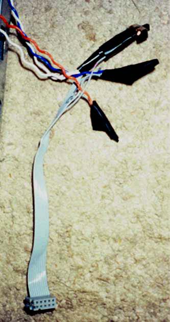 Figure 8 Front panel assembly connector For the LED you will need to get a 50-100ohm resistor placed in series on the cathode (+) side of the LED, and connect the anode (-) to the common ground. I have no clue what any of the other pins on the 10 pin connector do. If anyone has their proper functions I would be glad to hear from you. Proper CoolingAlthough PC cases have good air flow in the case you can’t guarantee the flow of air over the processor. I mounted a fan and pointed it over the processor. 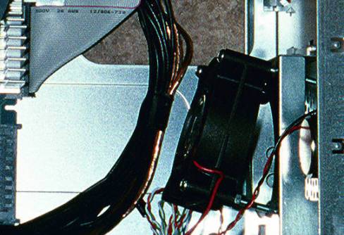 Figure 9 Cooling fan mounting position Before I had the fan installed the computer processor temperatures were up to about 45-50 degrees Celsius. Afterwards they fell to 30 deg. MAX.
Fit and Finished Product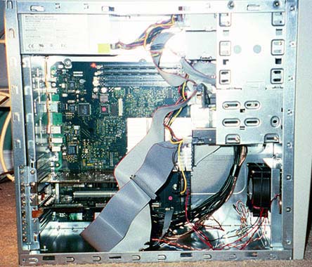 Figure 10 Finished, assembled case
Now you’re almost done. Throw in your hard drives and (NOTE: I assume Ian just left the back of the ATX's case open in the area where the case vendor's supply a snap-in panel with cutouts for PC ATX motherboard USB ports, etc. There are no panels pre-made for the Mac motherboards in this area, so you'd have to either hand make one or leave the area open.-Mike) | |
|
Intro | Page 2 | Page 3 | |
|
All brand or product names mentioned here are properties of their respective companies. Legal: Site Privacy and terms/conditions of use. |